The ASTER instrument configuration with the multi-telescopes
necessitates routine processing for the inter-telescope band-to-band
registration on the ground, unless the boresights are stable enough
during the mission life to keep the initial state after launch. The
pointing change mechanism is also a source of misregistration because
of limited accuracy of pointing position knowledge.
The important feature to be stressed here for the inter-telescope
registration is that a set of correction parameters will be valid and
can be applied to all images as long as the pointing is kept at the
same position and the elapsed time since a previous parameter setting
is short enough for boresight stability. The inter-telescope
registration correction will be carried out every observation unit,
using reference bands of each telescope (band 2 for VNIR, band 6 for
SWIR and band 11 for TIR).
There is no strong reason for this reference band selection,
although a matching experiment was carried out using simulated image
data. Band 2 was slightly better as a reference band than other VNIR
bands because of a relatively large atmospheric absorption in band 1
and a peculiarity of band 3 for vegetation. Band 6 is selected as
reference band of SWIR because it is one of the bands used for
parallax correction. Band 11 is selected as reference band of TIR
without any major reason.
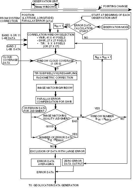
Figure 2-9 shows the inter-telescope geometric correction flows
for VNIR band 2. This correction process is carried out as follows.
- Start the registration error calculation at the beginning of
each observation unit.
- Select band 2 as a moving window image and band 6 or 11 as a
target image. The moving window is selected such that its center
corresponds to the lattice point at which the geometric correction
is carried out. The target image is selected to cover the search
area. The moving window image size is 41 x 41 pixels. The target
window size is larger than the moving window to cover the search
area.
- Select a cloud free window for the correlation by repeating
the previous item 2.
- Carry out the radiometric correction for the cloud free
images.
- Find the correlation coefficients by moving the moving window
in pixel units in both along-track and the cross-track directions.
- Find the point of highest correlation in sub-pixel units by
interpolating the correlation data calculation in the pixel unit.
- Evaluate the image matching quality. The criteria for judgment
is the correlation coefficient. The threshold value for the
correlation coefficient is set to 0.7 in the initial stage.
- Repeat the process from item (2) to item (7) a large number of
times (between 100 and 200), selecting other target images, to
enhance the accuracy by averaging.
- If the preset number of error data can not be reached in an
observation unit, the inter-telescope registration correction will
not be carried out. The failed information will be reported.
- Exclude the error data which deviates over 3s value from the average.
- The obtained number of the effective error data is averaged to
generate a set of final error data.
- Calculate 3s value to
evaluate the accuracy.
An evaluation of the algorithm was carried out using simulated
images generated from Landsat TM and airborne sensor images. The
registration accuracies in 3s
for SWIR/VNIR were 0.054 SWIR pixels and 0.051 SWIR pixels in the
cross-track and the along-track directions, respectively. The
registration accuracies in 3s
for TIR/VNIR were 0.050 TIR pixels and 0.044 TIR pixels in the
cross-track and the along-track directions, respectively. Judging
from these results a required accuracy of 0.3 pixels (3s) for the inter-telescope
registration will be achievable by averaging the image matching data
in the same observation unit, if the boresight of each telescope is
stable during a maximum observation time of 16 minutes. A hundred
data points will be enough for averaging to satisfy a required
accuracy of 0.3 pixels in 3s.

Figure 2-9 Inter-telescope geometric correction
flow
|