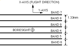
The large offset among SWIR bands in the along-track direction shown
in Figure 2-8(a) gives rise to parallax errors for band-to-band
registration depending on the distance between the instrument and the
targeted ground. The algorithm used for SWIR intra-telescope
registration is a combination of the image matching correlation
method and the coarse DEM method. The ETOPO-030 prepared by EROS
Data Center will be used as the coarse DEM.
A criterion of selecting band for image matching is good
correlation, consequently spectrally close. Bands 6 and 7 are
selected, although any other combination of neighbouring bands in the
2µm region will be available for this purpose. As shown in
Figure 2-8(a), detector arrays of bands 6 and 7 are located at
opposite ends of the focal plane to increase the parallax detection
sensitivity.
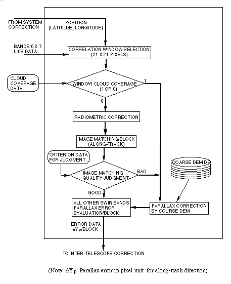
Figure 2-8(b) shows the parallax correction flow. In order to
eliminate this band-to-band misregistration due to the parallax, the
SWIR parallax correction process handles the image data as follows.
- Select band 7 as a moving window image and band 6 as a target
image. The moving window is selected such that its center
corresponds to the lattice point at which the geometric system
correction is carried out. The target image is selected to cover
the search area. The moving window image (band 7) size is 21 by
21 pixel.
- Select only cloud free windows for the correlation. Use the
coarse DEM data for cloudy windows.
- Carry out the radiometric correction for the two window
images.
- Find correlation coefficients by moving the window in the
along-track direction.
- Find the highest correlation point in sub-pixel units by
interpolating the correlation data calculated in pixel units.
- Evaluate the image matching quality. Criteria for judgment
are the correlation coefficient and the deviation from the
predetermined value from the coarse DEM data. The threshold value
for the correlation coefficient and the threshold deviation for
the predetermined value are set to 0.7 and 20% deviation,
respectively, in the initial stage. Use the parallax errors
calculated by the coarse DEM if the image matching quality can not
meet the criterion mentioned above.
- Evaluate the parallax error of all SWIR bands for the nadir
direction.
The registration error due to the parallax is evaluated at every
lattice point (the corner point of the block) and expressed with the
pixel unit for the Level-0B image data in the along-track direction.
An evaluation of the algorithm was carried out using simulation
images generated from airborne sensors and Landsat TM images.
Miss-registration due to parallax error was intentionally introduced
to these images using DEM data. Judging from these results 99 % of
the data are within 0.3 pixels for all images.
 (a) SWIR focal plane configuration
 (b) Parallax correction flow
Figure 2-8 SWIR focal plane configuration and parallax
correction flow
|