Depacketizing of CCSDS Level-0 Data:
The packets of each group are depacketized and aligned to recover the
unpacketized instrument source data by using a sequential counter,
flags in the primary header and time tags in the secondary header.
In the instrument source data format, the spectral band information
is multiplexed with the image in BIP (Band Interleaved by Pixel)
format as shown in Figure 2-2. Each swath line of image data is
appended by the instrument supplement data and spacecraft ancillary
data specific for the swath line.
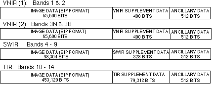
Figure 2-2 Instrument source data format
Demulitplexing Instrument Source Data:
The instrument source data are demultiplexed to separate image data for
every spectral band into BSQ (Band Sequential) format. Here, we have
the data rearranged in three groups, that is, the VNIR data group,
the SWIR data group and the TIR data group. Each data group consists
of the image data for each spectral band, the supplement data and the
ancillary data. For only the TIR data group, the short term
calibration obtained at the beginning of each observation is
included. The supplementary data are necessary for all of the data
groups to make it possible to process them independently. In this
stage the image data are not divided into scenes but kept in one
continuous observation unit, that is, a long strip of image data for
more flexible scene selection. This data set is defined as Level-0A
data which is a tentative product only used during processing.
Image Data Stagger Realignment:
For SWIR
and TIR image data the Level-0 pixel addresses are changed, so that
all pixels for each band lie on one line, compensating for the
staggered configuration described below. This realignment process is
carried out not only to have more exactly aligned image data without
resampling for the image matching process but also to simplify
subsequent processes.
The SWIR subsystem uses electronically scanned linear detector
arrays for each band to obtain one data line simultaneously in the
cross-track direction for each scan period. These detector arrays
are separated for odd and even numbered detectors with a staggered
configuration as shown in Figure 2-3(a). The realignment for SWIR
pixel addresses is carried out to compensate for the difference from
the center line between the odd and the even lines. The stagger
offset value to the center line can be set to ± 1 pixel with a good approximation.
TIR images are obtained by mechanical scanning with 10 detectors
for each spectral band, that is, 50 detectors in total. Ten
detectors for each band are arranged with the staggered configuration
in the cross-track direction as shown in Figure 2-3(b). The
realignment for TIR pixel addresses is carried out to compensate for
the difference from the center line between the odd and the even
lines. The stagger offset value to the center line can be set to
± 4 pixels with a good approximation.
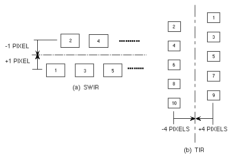
Figure 2-3 Realignment positions of staggered SWIR and TIR pixels
|