Common: Radiometric coefficients are generated
in two steps. The first step is an off-line process from Level-1
data product generation to prepare radiometric coefficients at
predefined reference temperature. These coefficients will be
effective for a long time, depending on the instrument stability, and
available in radiometric correction data base files along with the
temperature coefficients. One set of offset and sensitivity data are
necessary for the VNIR and SWIR bands and one set of offset, linear
sensitivity and nonlinear sensitivity data are necessary for the TIR
bands. Destriping parameters will be generated from the image data
if necessary, analyzing the image data obtained during the initial
checkout operation period.
The second step is an on-line process executed during Level-1
product generation to correct the radiometric coefficients for
instrument conditions such as detector temperature and dewar
temperature, which may change for every observation.
Generation of Radiometric Correction Data Base:
The radiometric coefficients for the reference temperatures were
evaluated during the preflight test period using integration spheres,
followed by a regular evaluation during the inflight period with
on-board calibration and vicarious calibration data, and then updated
if necessary. On-board calibration is scheduled every 17 days to
check the stability.
These radiometric coefficients are available in the radiometric
correction data base with temperature coefficients as on-line
parameter files applied in the Level-1 processing. All temperature
coefficients were prepared during the preflight test period and will
be used throughout the mission period.
The required absolute accuracies are 4% (s) for VNIR and SWIR, and
1 to 3K for TIR depending on target temperatures.
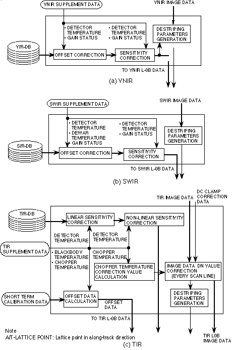
Generation of VNIR Observation-Unit-Specific
Radiometric Coefficients: Figure 2-4(a) shows the VNIR
radiometric coefficients generation algorithm flow. Detector
temperature is the only reference parameter by which the radiometric
coefficients (offset and sensitivity) have to be corrected for a
specific observation unit data set. Under normal operating conditions
within the designed temperature range, this correction process will
not be necessary, since the correction value is expected to be very
small.
Generation of SWIR Observation-Unit-Specific
Radiometric Coefficients: Figure 2-4(b) shows the SWIR
radiometric coefficients generation algorithm flow. Detector
temperature and dewar temperature are the reference parameters by
which the radiometric coefficients (offset and sensitivity) have to
be corrected for a specific observation unit data. Under normal
operating conditions the detector temperature is controlled to within
±0.2 K at around 77 K. Therefore the correction process for
detector temperature will not be necessary as long as the SWIR is
operating normally .
The dewar temperature correction, which is necessary for
compensating only for thermal radiation from the dewar, is applied
only to the offset, since the SWIR detector is sensitive to room
temperature thermal radiation up to 5 µm and the band pass
filter can not completely remove this out-of-band radiation. The
dewar temperature is used as a representative value for the internal
thermal radiation.
Generation of TIR Observation-Unit-Specific
Radiometric Coefficients: Figure 2-4(c) shows the TIR radiometric
coefficients generation algorithm flow. The linear and the non-linear
sensitivities coefficients in the data base are corrected only by the
detector temperature. Under normal operating conditions the detector
temperature is within ±0.2 K at around 80 K. Therefore,
correction for the detector temperature will not be necessary as long
as TIR is operating normally.
The offset data, common throughout the observation unit, are
generated from the short term calibration data acquired at the
beginning of each observation by using the blackbody temperature in
the TIR supplementary data.
The correction for the offset data due to chopper temperature is
calculated using the chopper temperature changes from the short term
calibration period. The chopper temperature correction is carried out
on the TIR Level-0A image data with the DC clamp correction. This
correction will be possible for each scan data (each ten lines of
data in the along-track direction), since the chopper temperature
data is included in the supplementary data.
This image data correction will result in slightly different TIR
Level-0B image data DN values from Level-0 data. The Level-0 data is
digitized to 12 bits. The LSB (Least Significant Bit) value of
Level-0B image data is very small compared to
NEDT (less than one third for
the 300 K target). Therefore, this difference will not give rise to
any significant round-off error.

Figure 2-4 Radiometric correction coefficients generation
flow
TIR DC Clamp Correction: TIR output voltage is
clamped at -1.4 V ±
DVn for bands 10-12
and -0.9 V±
D Vn for bands 13 and
14 when the chopper plate is observed by the detectors at every scan.
The small voltage D
Vn is the noise voltage at the moment of the clamp
which changes randomly in every scan and must be corrected to exactly
set the clamp voltage.
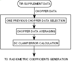
Figure 2-5 shows the TIR DC clamp correction flow. The exact
clamped output (DN value) is available in the TIR supplementary data
as the chopper data. The chopper data in the one previous scan are
used for the correction. The 100 chopper data acquired for one scan
are averaged to reduce noise component, followed by the DC clamp
error calculation which corresponds to ±
D Vn . This clamp
error is transferred to the TIR radiometric correction module to
subtract it from the TIR Level-0A image data to generate Level-0B
image data.

Figure 2-5 TIR DC clamp correction
|