Engine Combustion and Emission Control Group
Objectives
We perform a fundamental and advanced research associated with the engine combustion and after treatment technology to resolve the common problems that automotive manufacturers have encountered. On the other hand, we also develop the practical technology that can be immediately used for improvement of engine thermal efficiency to contribute to the reduction of fossil fuel use and CO2 emission. In the meantime, we endeavor to establish the domestic and international standard of automotive fuels.
Research topics
- Fundamental Research of Engine Systems for Industrial Needs
- Vehicle simulation modeling
- Investigation of deposition mechanism of EGR systems
- Investigation of prediction technology for the performance and degradation of exhaust gas treatment system
- R&D of Next Generation Engines
- New fuel engine system
- Innovative spray, ignition and combustion technology
- Standardization of Fuels for Vehicles
- International and national standardization of dimethyl ether (DME) fuel
Members
| Group Leader |
UCHISAWA Junko (内澤 潤子) |
|---|---|
| Members |
KINOSHITA Koichi (木下 幸一) MIZUSHIMA Norifumi (水嶋 教文) SUZUKI Shunsuke (鈴木 俊介) KUZUOKA Kohei (葛岡 浩平) OGUMA Mitsuharu (小熊 光晴) |
| Invited researcher |
TAKEDA Yoshinaka (武田 好央)
HIGURASHI Kazuaki (日暮 一昭) |
| Technical staff |
TSUKAZAKI Yoshiko (塚﨑 好子)
ABE Yohko (阿部 容子) YAMAMOTO Asuka (山本 明日香) |
Research Topics
Development of Advanced Engine Combustion and Aftertreatment Technologies
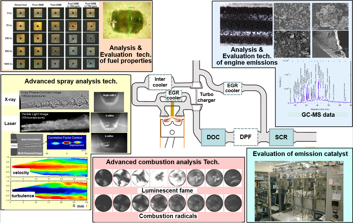
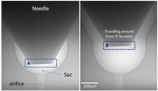
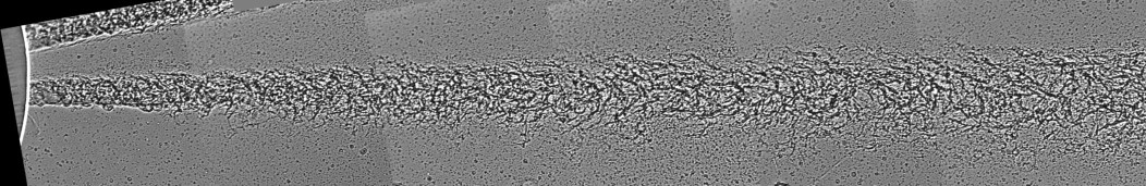
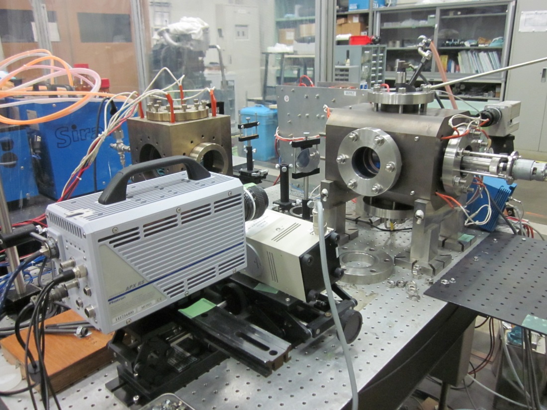
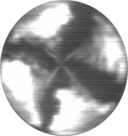
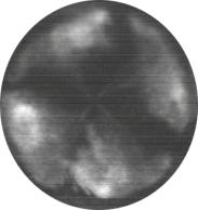
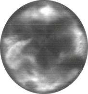
Fluid-dynamics diagnostic using X-ray imaging techniques
|
Fluid dynamics diagnostic using the synchrotron X-ray imaging techniques (SPring-8 & Argonne National Laboratory) - A novel method to measure the fluid dynamics in the optical dense region ⇒ To establish new numerical models |
【Synchrotron X-ray souces】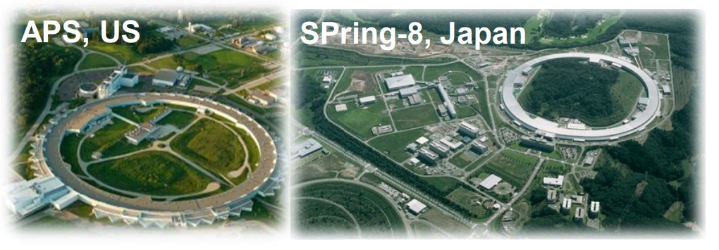
|
|
< C.Near-nozzle spray dynamics >
| ||||
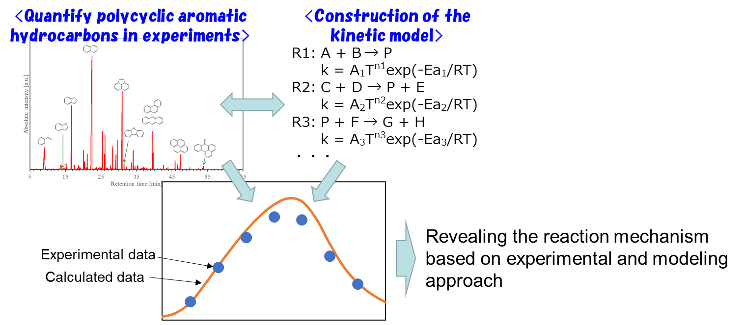
Revealing the formation mechanism of polycyclic aromatic hydrocarbons
- It is necessary to reduce an emission of polycyclic aromatic hydrocarbons
- For that purpose, revealing the reaction mechanism is required

- To quantify the concentrations of polycyclic aromatic hydrocarbons formed in a combustion reaction using a flow reactor
- To construct the kinetic model based on experimental data
- To reveal the reaction mechanism of polycyclic aromatic hydrocarbons using experimental and modelling results
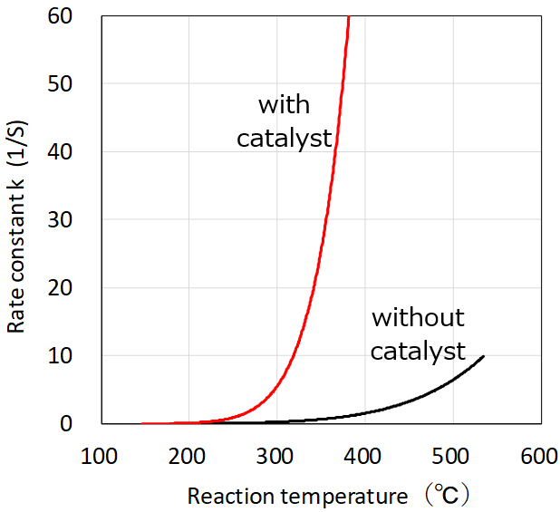
- Experimental determination of rate constants on exhaust gas purification reactions
- Acquisition of fundamental data for model-based development of zero-emission automobile
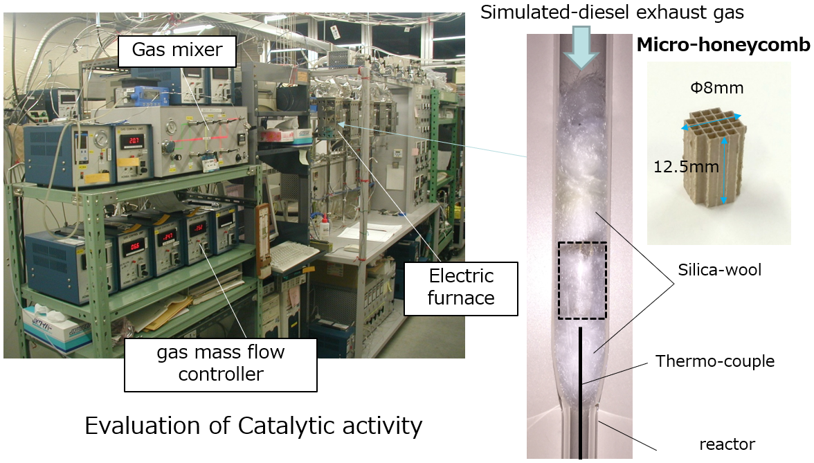
- We have developed a simple evaluation method to estimate catalytic activity on a scale of 1:10,000 of actual engine conditions using simulated laboratory gas conditions.
- Rapid evaluation of catalytic activity can be expected to lead to improvements at an early stage.
- In order to reduce CO2 emissions from automobiles, there is an urgent need to make fuel or electric energy more carbon-free and to save energy by improving fuel and electricity efficiency.
- In this research, our group focus on energy conservation, and analyze in detail the use route of fuel or electricity-derived energy consumed by a single vehicle using a vehicle simulation model, and propose an effective way to use waste heat and energy loss through the appropriate use of electrification technology.
- Build a vehicle simulation model for energy flow analysis from vehicle test data
- Use Modelica language (an open-source, acausal modeling language) for the vehicle simulation model.
- Examine total vehicle energy management technology through simulation, taking into account electric components, air conditioning, and new devices (thermoelectric conversion devices, catalytic heaters, etc.)
- GC-FID,GC-MS
- HPLC
- NMOG, etc.
|
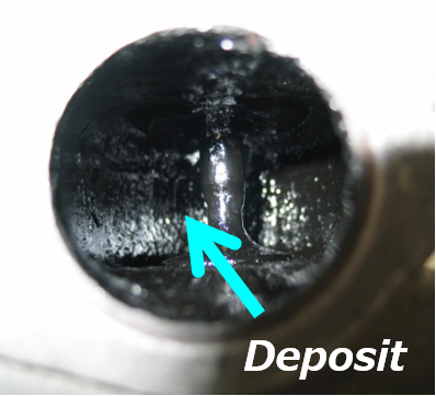
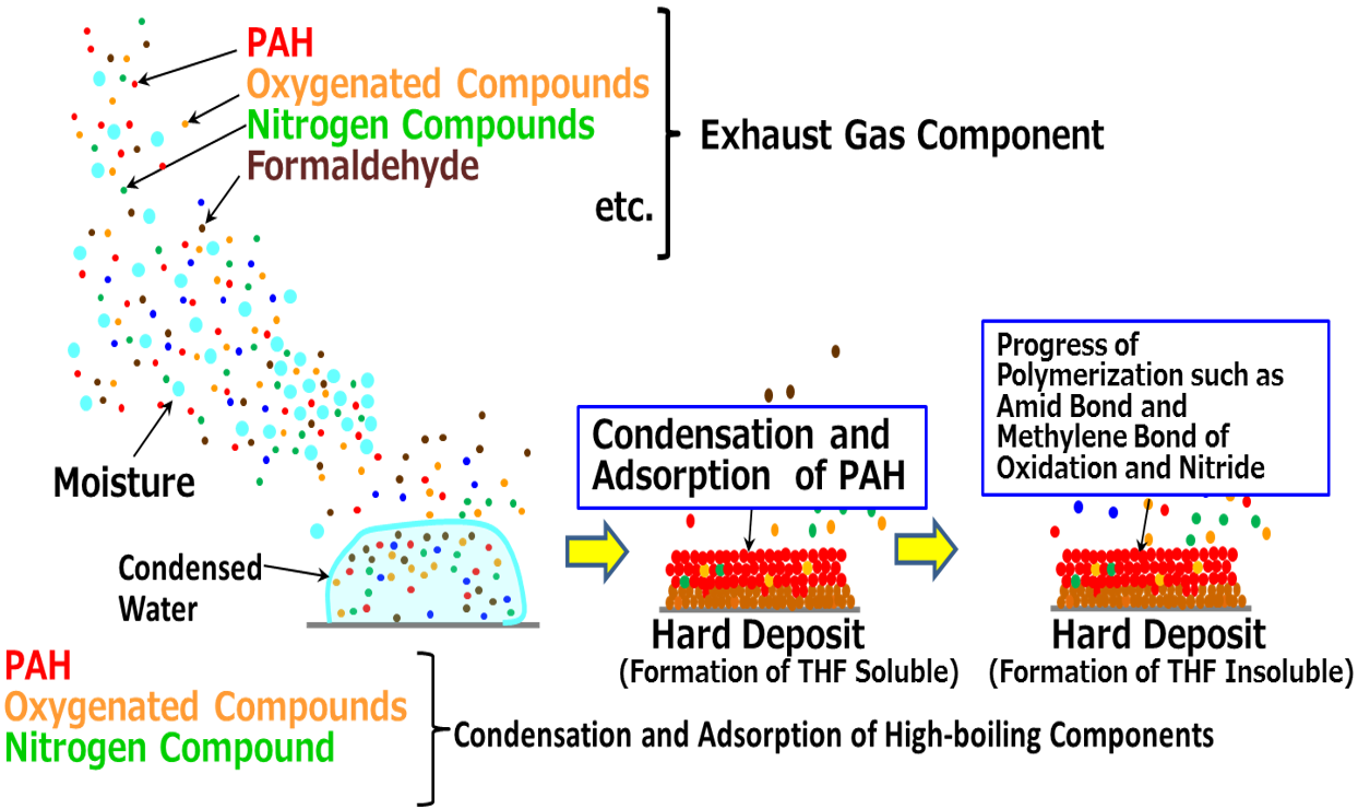
Elucidation of the mechanism of EGR deposit generation
|
[ Background / Purpose ]
Expanding the introduction area of EGR due to Tightening emission regulations such as RDE and Type 6 test is an important issue.
It is necessary to develop a reliable EGR system that complies with emission regulation.
[ Method ] Estimate, verify and elucidate of EGR deposit formation from the results of detail chemical analysis of the exhaust gas and deposit. |
|
Introduction the EGR system under rich combustion and low temperature expands the environment in which EGR deposits accumulate.
⇒ Common issue for each company |
|
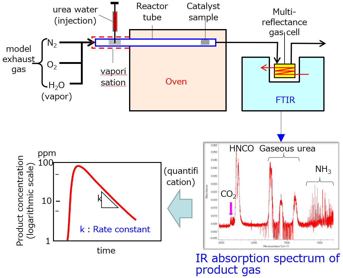
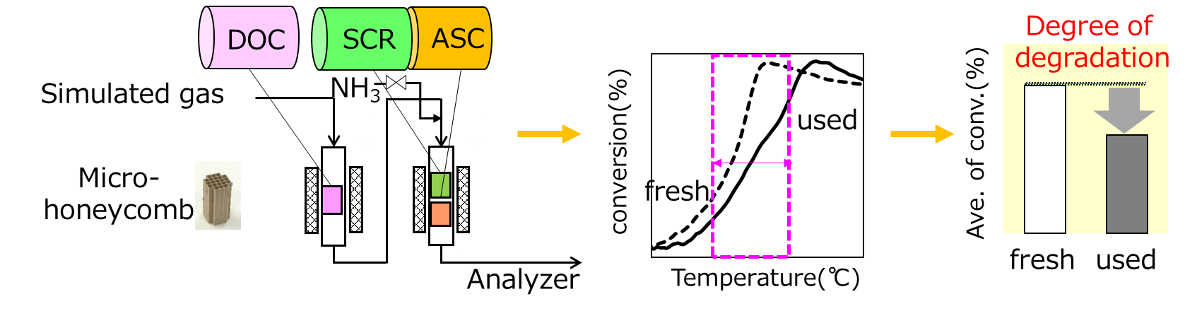
Measurement of reaction rates for automotive exhaust gas purification systems
|
|
|
|
 Decomposition rate of urea to NH3 |

|
|
Total Performance Evaluation of Diesel Selective Catalytic Reduction Catalyst System through Lab-scale Experiments
|
Research on Energy Management for Mobility
[ Summary of the study ]
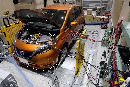
[ Research Methods ]
Vehicle experiments using a chassis dynamo
|
|
Vehicle simulation modeling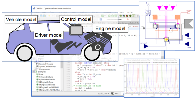
|
Example of a vehicle simulation model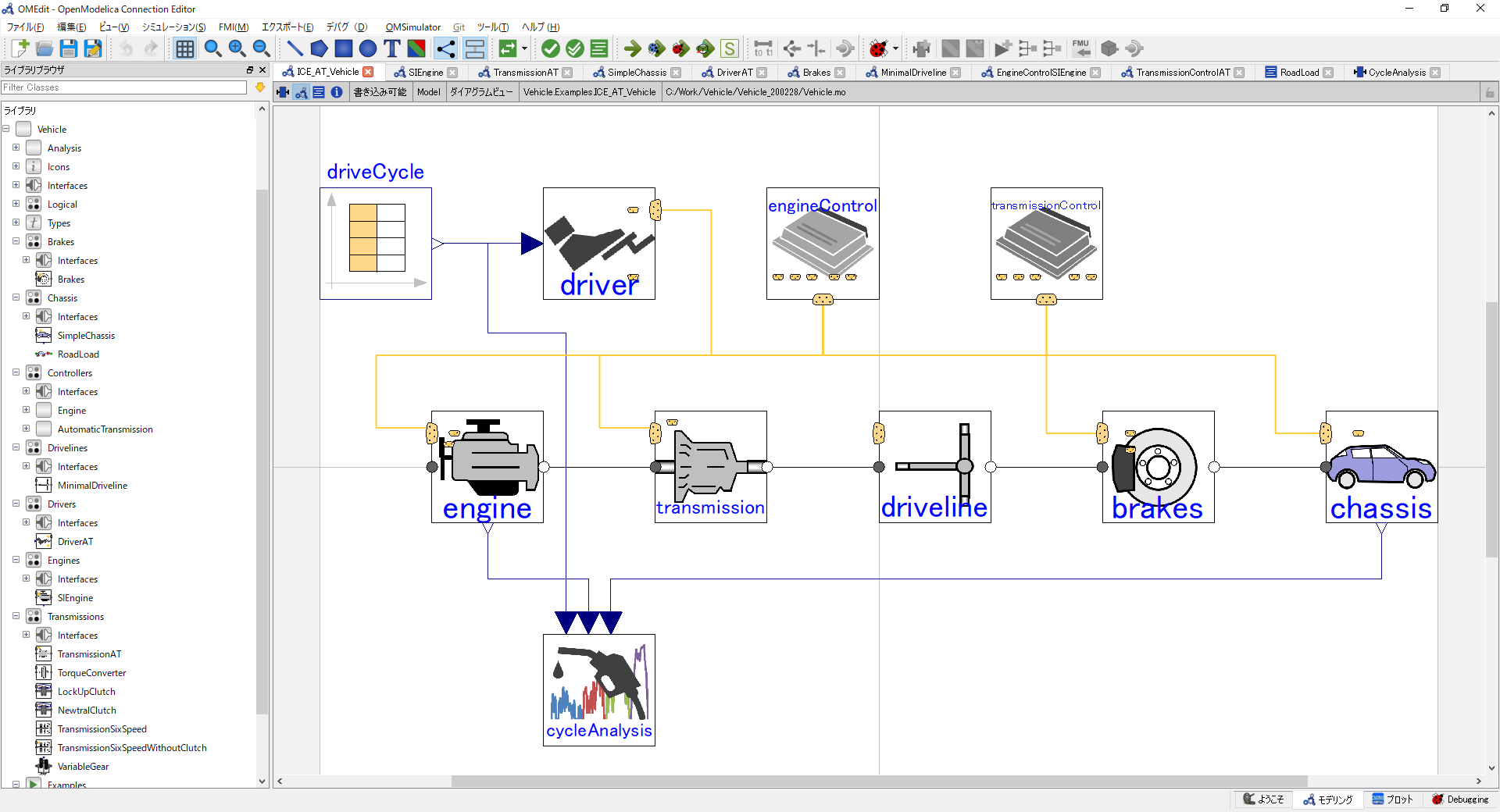
|
Example of fuel consumption calculation results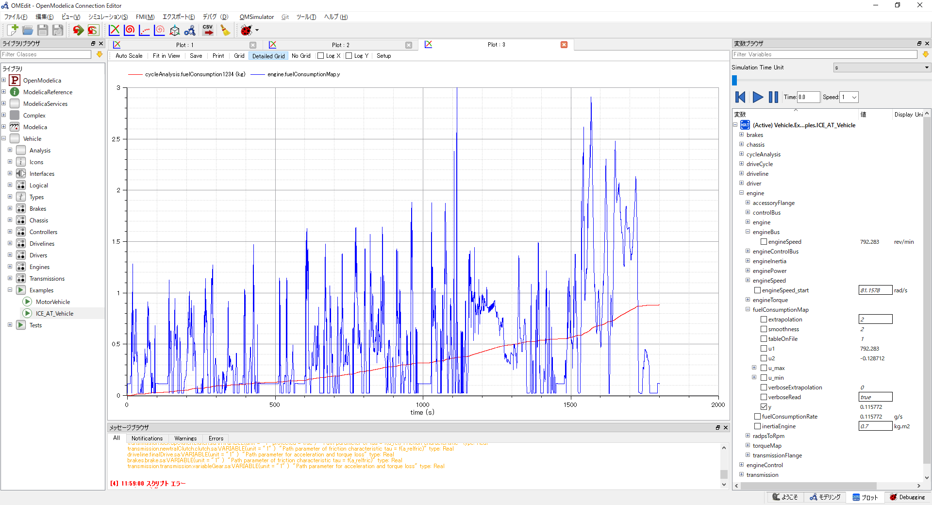
|
Experiment Facility
Spray observation-combustion chamber
|
(Left)Optical engine for combustion visualization (Below) DME Direct injection Combustion visualization
| ||||
|
(Left) Spray observation combustion chamber (Below) Fuel spray visualization 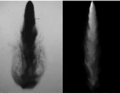
|
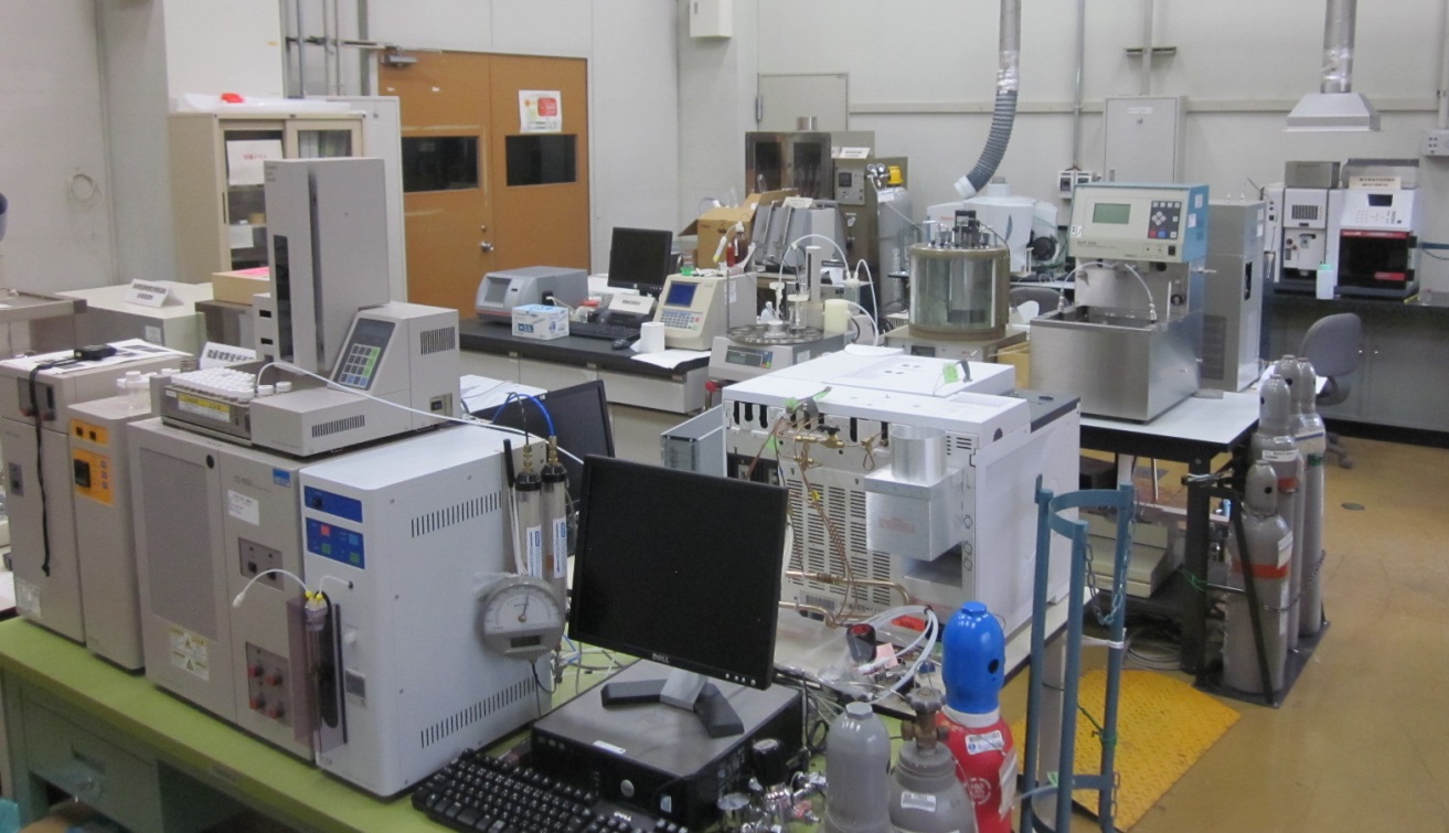
Catalyst Testing Room
 |
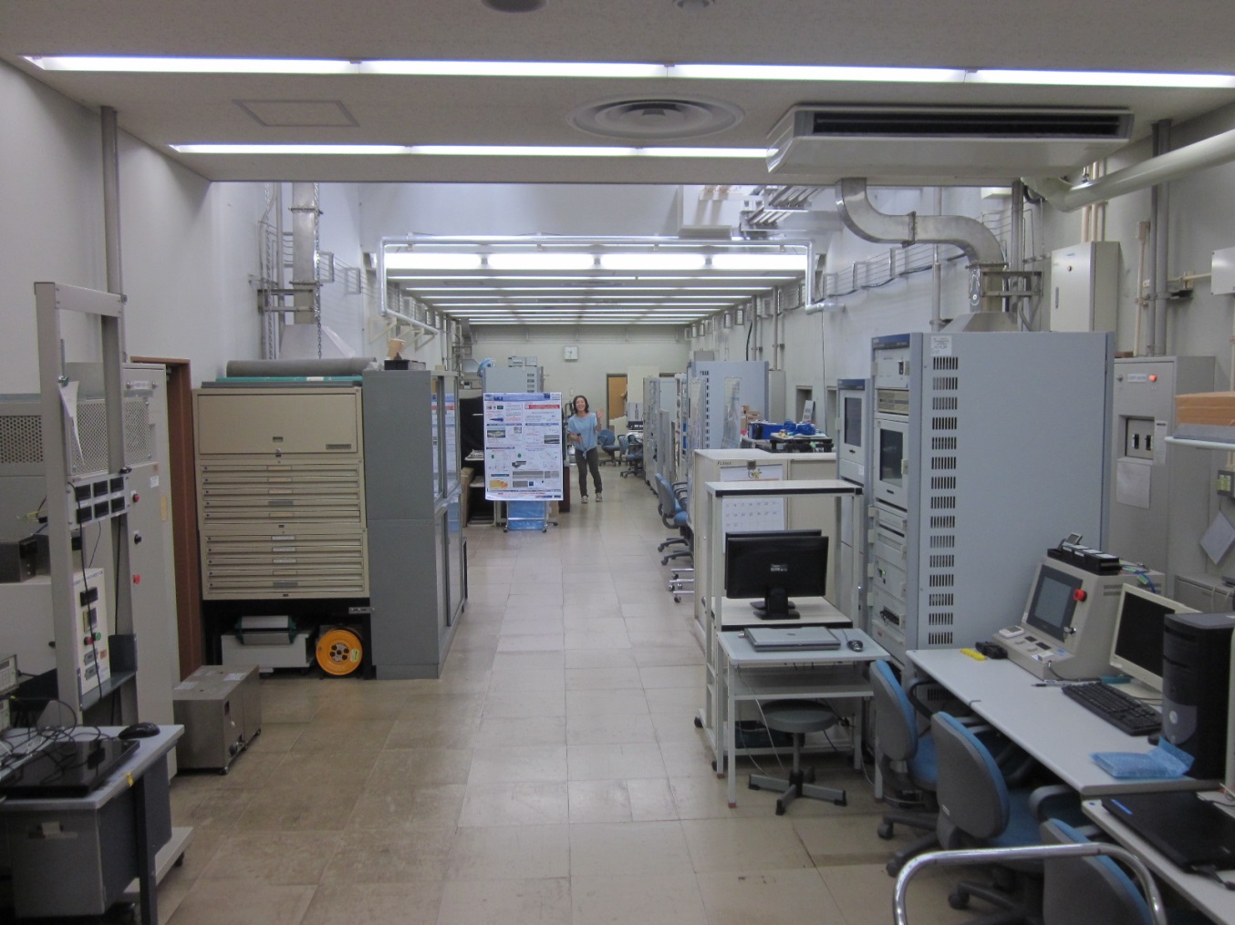
Chemical Analysis Room
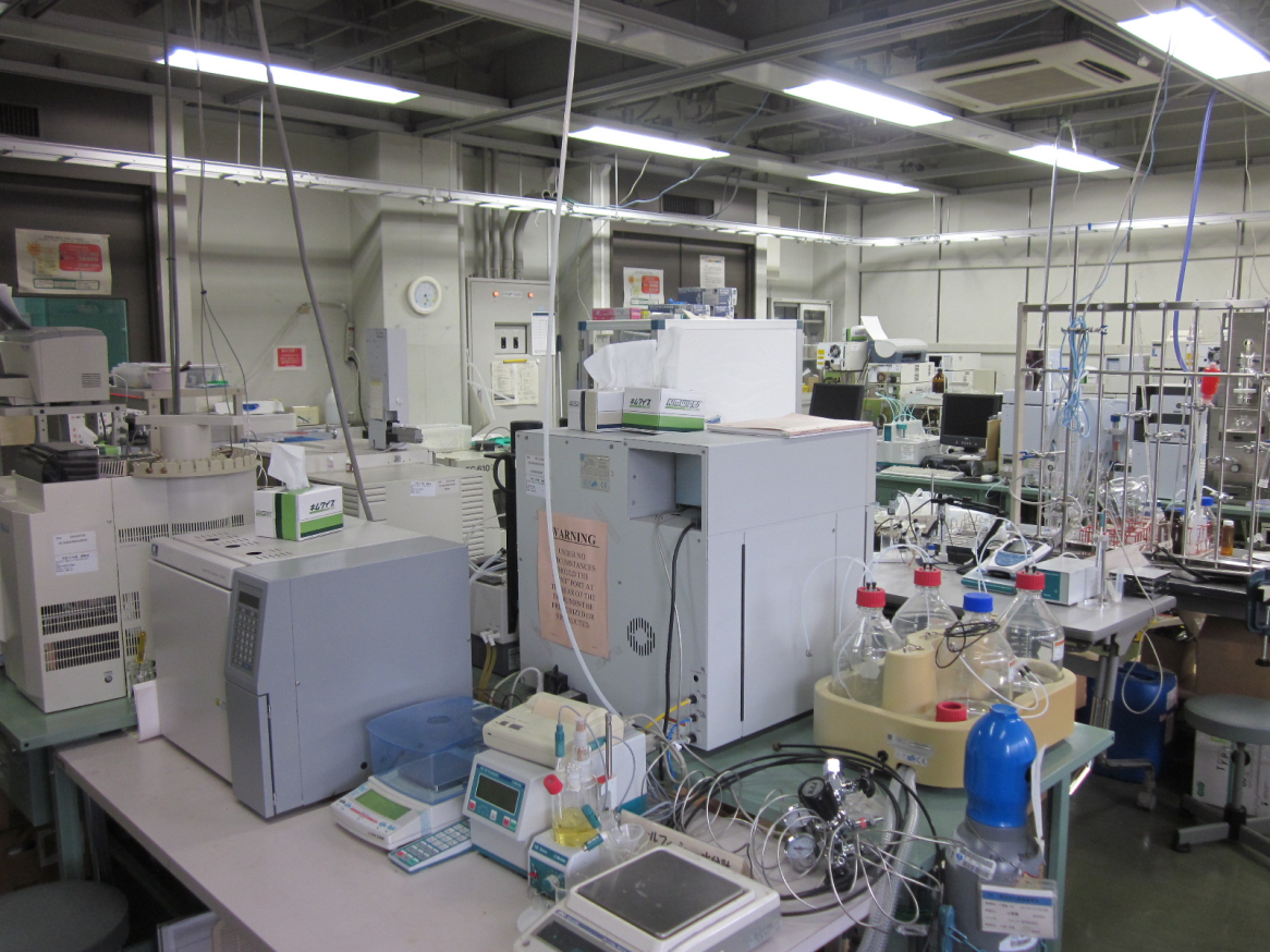  |
Gas emission, fuel characteristics,deposit detail analysis |
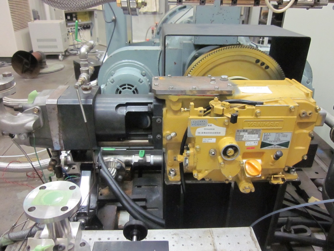
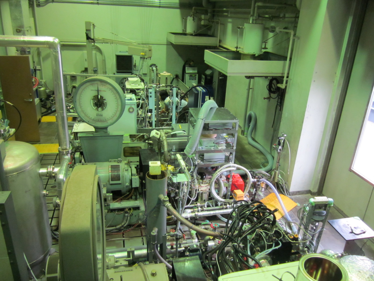
Engine Test Bench & Engine Bench Control Room
|
Engine Test Bench |
|
Single cylinder 638cc diesel engine 
|
Single cylinder 2,000cc diesel engine Cam-less system & ultra high pressure injector 
|
|
Engine Bench Control Room | |

|
Engine dynamometer control panel | |

|
Exhaust gas analysis and measurement devices |
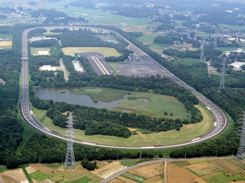
Test Circuit & Dynamometer Room
|
3,200m AIST Tsukuba Center North Site 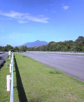
| |
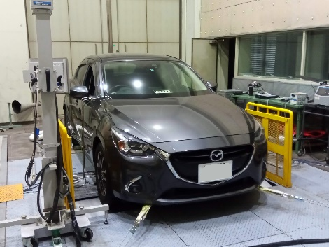 Dynamometer Room
| ||
Contact
Engine Combustion and Emission Control Group
E-mail :ec2-info-ml*aist.go.jp (* must be replaced by "@")
Address : 1-2-1 Namiki, Tsukuba, Ibaraki 305-8564 Japan ( AIST Tsukuba East )
updated on 2023. 04. 04