※2022/11/25 : Suspend "AIST Gait Database 2019" distribution.
Release of AIST Gait Database 2019
As the national research institute in Japan, we started to provide a large volume (more than 100), raw dataset measured by optical motion-capture-system (AIST Gait Database) in 2013. In “AIST Gait Database 2013,” marker-name labeled raw data measured by optical motion-capture system of one gait cycle (right heel contact to next right heel contact) obtained from 139 participants were included. Two years later from our first open database, we started to distribute “AIST Gait Database 2015.” In this database, motion-capture-system data of five gait cycles (right heel contact to next right heel contact) obtained from 214 participants were included. However, these data of gait cycles were all started from right heel contact, and therefore could not mention the difference between right and left leg. In order to solve this problem, we started to distribute new database “AIST Gait Database 2019.” In this database, motion-capture-system data of ten gait cycles (5 gait cycles started from right heel contact and 5 gait cycles started from left heel contact) obtained from 300 participants were included.
Upadate Log
- 2020/3/12:English page of AIST Gait Database 2019 released.
- 2020/12/1:Contact address has been changed.
- 2021/2/26:The skeltal model has been corrected.
About Gait Database 2019
- (1)Introduction
- (2)Measurement Environment and Instruments
- (3)Marker-set Guideline
- (4)Model Definition
- (5)CMO File
- (6)Procedure of Visual3D Reader
- (7)Demographics of the Participants
- (8)Privacy Policy
- (9)Citation
- (10)Inquiries and data acquisition
(1)Introduction
In this section, we will illustrate the details of gait data and the usage of Visual3D reader.
(2)Measurement Environment and Instruments
Data acquisition was performed in a room with a straight 10m path for the participants to walk on. Three-dimensional position data of 55 to 59 reflective markers attached to the participants’ body landmarks and ground reaction forces (GRFs) were obtained using a 3D motion-capture-system (VICON MX, Oxford, UK) with a sampling frequency of 200 Hz, and force plates (AMTI, Watertown, MA, USA) sampled at 1000 Hz (Fig. 1). The participants were asked to walk barefoot at a comfortable, self-selected speed. Before the walking trials, the positions of the markers were recorded while standing stationary. The participants were then allowed sufficient practice walks to ensure the maintenance of the natural gait. After the practice, ten gait cycles (five from the right leg and five from the left leg), as determined by force plates, were recorded. The raw data was digitally filtered using a fourth-order Butterworth filter with zero lag and a cut-off frequency of 6 Hz for the trajectories and 10 Hz for the GRFs. The study protocol was approved by the local ethical committee.
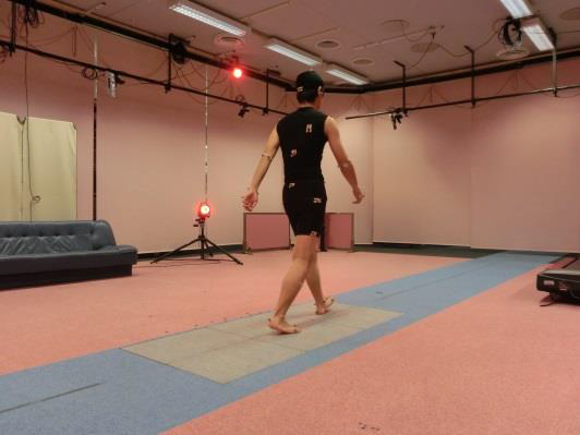
Image of measurement environment
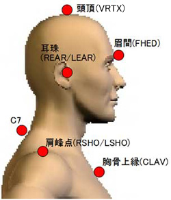
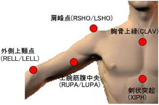
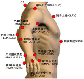
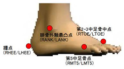
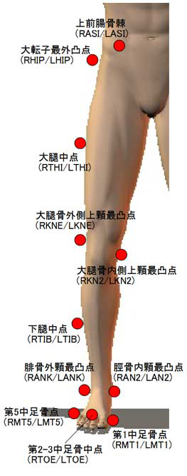
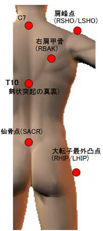
(3)Marker-set Guideline
The marker-set used during gait trials are as follows. Some markers have been added depending on data measurement time. However, the fundamental markers required to define each segment have not changed.
 |
 |
 |
 |
 |
 |
(4)Model definition
This section describes model definition and coordinated systems for performing kinematic and kinetic analysis.
4.1 Pelvis
The pelvis was defined by the sacral point and the left and right anterior superior iliac spines (ASIS) based on Davis et al., (1991).
Origin: the mid-point of the right and left ASIS markers
Coordinate axis:x-axis:The vector that pass through the left and right anterior superior iliac spine from the origin
y-axis:The vector that is the cross product of axis from origin to sacral point and x-axis
z-axis:The vector that is the cross product of x-axis and y-axis
[Reference]Davis RB, Ounpuu S, Tyburski D, Gage JR. (1991) "A
Gait Analysis Data Collection and Reduction Technique." Human Movement
Science, 10: 575-587.
Visual3D description site:http://c-motion.com/v3dwiki/index.php?title=Helen_Hayes_(Davis)_Pelvis
4.2 Lower Body
The thigh, shank, and foot define a coordinate system as follows.
Thigh:
Distal end:The mid-point of lateral epicondyle and medial epicondyle of the femur
Proximal end (Origin):Hip center(Calculated in 4.1 section)
Coordinate axis:
z-axis:The vector from distal end to proximal end
y-axis:The vector that is the cross product of axis through lateral epicondyle and medial epicondyle of the femur
x-axis:The vector that is the cross product of z-axis and y-axis
Shank:
Distal end:The mid-point of lateral malleolus and medial malleolus
Proximal end (Origin):The mid-point of lateral epicondyle and medial epicondyle of the femur
Coordinate axis:
z-axis:The vector from distal end to proximal end
y-axis:The vector that is the cross product of axis through lateral epicondyle and medial epicondyle of the femur
x-axis:The vector that is the cross product of z-axis and y-axis
Foot:
Distal end:The mid-point of the first and fifth metatarsal head
Proximal end (Origin):The mid-point of lateral and medial malleolus
Coordinate axis:
z-axis:The vector from distal end to proximal end
y-axis:The vector that is the cross product of axis through lateral epicondyle and medial epicondyle of the femur
x-axis:The vector that is the cross product of z-axis and y-axis
Visual3D description site: http://www.c-motion.com/v3dwiki/index.php?title=Segments
For the definition of the position of the center of mass and segment mass, select the [Model Viewer]tab from Visual3D Reader and double-click the name of each segment in the list to see how each segment was defined.
4.3 Upper body
The upper body model is modeled similarly to the lower body, but differs in how the proximal and distal ends are defined.
The Golem Upper body Model was used to create this database. Refer to Visual3D Wiki for more details.
Visual3D description site: http://c-motion.com/v3dwiki/index.php?title=Tutorial:_Golem_Upperbody_Model_Delete
4.4 Degrees of Freedom Joint Angle
In this database, each joint angle is defined as having three degrees of freedom.
4.5 Definition of Joint Angle
Each joint angle is defined as a three-dimensional relative angle of the distal segment from the proximal segment with respect to the pelvis.
At this time, the x-axis represents flexion and extension, the y-axis represents adduction and abduction, and the z-axis represents internal and external rotation.
Note that with this definition, the posture of the ankle joint when standing is not 0 degrees. In other words, the ankle joint angle is always calculated as a 60 degrees dorsiflexion in a standing posture.
The order of rotation of the three-dimensional angle is x,y,z in accordance with the definition of Cardan angle.
However, in this database, it has been confirmed that if the shoulder joint angle is described in this order, problem may occur in the angle calculation depending on the subject.
This is because the x-axis coordinate of the upper arm is calculated by the landmark of the elbow, and there is a subject whose humerus rotates more than 90 degrees during walking.
It can be solved by modifying the rotation order, but in this database, it is left as it is in order to match it with other joint angle data.
4.6 Definition of Pelvis Angle
Because the pelvis angle is calculated as an angle in the laboratory coordinate system, the angle around the z-axis is not calculated correctly depending on the direction of walking. Therefore, two pelvis angles, PelvisAnglePositive and PelvisAngleNegative, corresponding to each direction of walking are calculated, so please use them appropriately.
4.7 Definition of Joint Moment
Joint moment uses the same definition as joint angle. In other words, it is recorded as the joint moment of the distal segment described in the proximal segment coordinate system with the pelvis as the center. In this database, ground reaction force data is accurately measured only from the heel contact to the heel contact one cycle later. Although moments of contra-lateral leg and lower back are also calculated, ground reaction force data of contra-lateral leg immediately after heel contact is not measured in some cases. As a result, it should be noted that these moments of contra-lateral leg and lower back may not be accurate.
4.8 Notation of Ground Reaction Force
As shown in Section 4.7, the ground reaction force data is measured from the heel contact to the heel contact one cycle later, and the ground reaction force data during the heel contact on the contra-lateral side during that period is also measured. Similar to the definition of the angle of the pelvis in Section 4.6, the ground reaction force data and center of pressure data during walking define the right direction of the subject as the positive of the x-axis and the direction perpendicular to the ground as the positive of the z-axis in the laboratory coordinate system.
4.9 Definition of Joint Power
Joint power is expressed as the product of joint angular velocity and joint moment. In this database, we calculated the joint power around the distal joint axis based on the proximal segment coordinate system. A positive joint power indicates concentric muscle activity, whereas a negative power indicates eccentric muscle activity.
(5)CMO File
An individual CMO file (the format for Visual3D software) has been created for each subject. The contents of the CMO file consist of two parts: standing posture data and walking data, both of which were measured using the Vicon system at AIST.
Subject information is described in the file name. The format of the file name is as follows.
Example 1)0001_01_F_70_152_46.CMO
Example 2)0009_01_M_69_163_51.CMO
- 1st-4th characters:ID
- 6th-7th characters: Repetition number
- 9th character:Gender(M:Male/F:Female)
- 11th-12th characters:Age
- 14th-16th characters:Height (cm)
- 18th-19th characters:Weight (kg)
In each CMO file, the data of ten gait cycles (five gait cycles start from right heel contact and five gait cycles start from left heel contact) was included. In addition, CMO files are basically created with sequential numbers, but those for which data for ten trials could not be obtained due to some reason, such as missing markers, were omitted.
(6)Procedure of Visual3D Reader
About Visual3D Reader
Free Visual3D Reader is a CMO file viewer released by C-motion for free. Currently, it can be downloaded from the following under the name of Free CMO Reader.
After installation, the name will be “Visual3D Free Reader”. In this section, the name “Visual3D Reader” is used for convenience.
https://c-motion.com/tools.php
Procedure 1
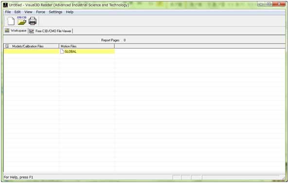
Start Visual3D Reader. When it starts up, a window like the one below is displayed.
Procedure 2
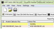
[File]→[Open/Add] opens the file selection dialog. Select the CMO file you want to view.
Procedure 3
When you double-click a c3d file under Motion Files, the screen changes to the animation viewer screen.
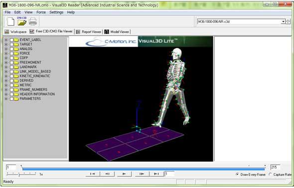
In the graphic screen, you can rotate and scale by pressing and moving the mouse button.
- Move mouse with left-click→ rotate
- Move mouse with right-click→ scale
- Move mouse with left/right click→ translation
You can move the animation with the > button below.
Procedure 4
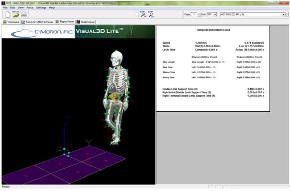
If you select report viewer tab, you can see the information of the subject while walking.
- Page 1:Time factor(gait cycle, etc.)and distance factor(step length, etc.)
- Page 2:Ground reaction force data/ center of pressure data
- Page 3:Lower body joint angle data/ pelvis angle data
- Page 4:Upper body joint angle data
- Page 5:Lower body joint moment data
- Page 6:Lower body joint power data
Procedure 5
Select the [Free C3D/CMO File Viewer] tab and click on the folder column on the left to see various information.
- EVENT_LABEL:Gait events (heel-contact, toe-off etc.)
- TARGET:Marker position
- Original:Measurement raw data
- PROCESSED:After filtering data(10Hz low-pass filter)
- ANALOG:Output information of each force plate(Not generally used)
- FORCE::Ground reaction force data for each force plate
- Original:Measurement raw data
- PROCESSED:After filtering data(10Hz low-pass filter)
- COFP::Center of pressure data for each force plate
- Original:Measurement raw data
- PROCESSED:After filtering data (6Hz low-pass filter)
- FREEMOMENT:Moment data for each force plate(Not generally used)
- LANDMARK:Virtual marker positions in the laboratory coordinate system defined using the marker positions, such as joint center
- LINK_MODEL_BASED:Calculation data such as joint moment and joint angle
- KINETIC_KINEMATIC:Kinematics and kinetics information for each segment(Not generally used)
- DERIVED:Rotation information around axis for each segment(Not generally used)
- METRIC:The height and weight of the subject, information for data normalization
- FRAME_NUMBERS:Time information(Not generally used)
※Make sure the upper right dialog is the file name.If this is GLOBAL or ALL_FILES, left click will not be possible. If it is not, click the dialog and select a file name.
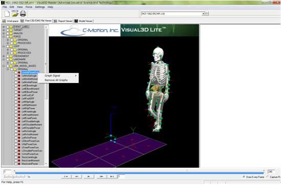
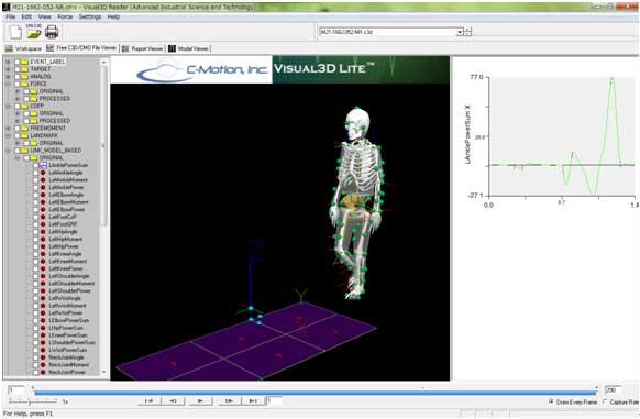
Right-click:A graph can be described in the rightmost area.
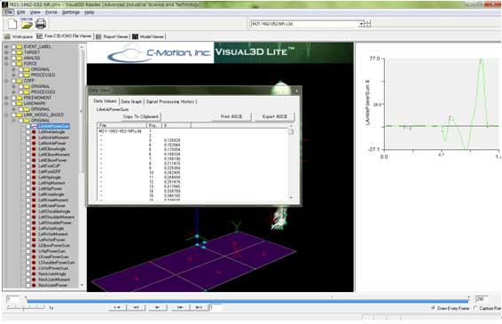
Left-click:You can export the data to text file with [Export ASCII].
(7)Demographics of the Participants
- Archive folder:\2019_DHRC_GaitDatabase_Original\CMO
- Number of participants: 150 males and 150 females
- Age range: 20 to 78 years
- Height:138cm to 185cm
- Weight:34kg to 105kg
- Data size:7.60 GB / Number of files:300
(8)Privacy Policy
The feature of this database is not the statistical data of the whole group but the individual data of the subjects who cooperated in the measurement. The consent has been obtained from all the subjects regarding implementation of open data access.
(9)Citation
When referring our database, please refer as follows.
- Yoshiyuki Kobayashi, Naoto Hida, Kanako Nakajima, Masahiro Fujimoto, Masaaki Mochimaru, 2019: AIST Gait Database 2019.
https://unit.aist.go.jp/harc/ExPART/GDB2019.html
(10)Inquiries and data acquisition
※2022/11/25 : Suspend "AIST Gait Database 2019" distributionThose interested in using AIST Gait Database, please contact AIST Gait Database Department by e-mail. We will get back to you with a questionnaire and usage agreement form.
- Name
- Affiliation(company name, school name etc.)
- Contact email address
- Name of database which you wish to apply(In the case of this database, "AIST Gait Database 2019")
- Intended purpose(to the extent possible)
National Institute of Advanced Industrial Science and Technology (AIST)
AIST Gait Database Department
harc-liaison-ml@aist.go.jp